
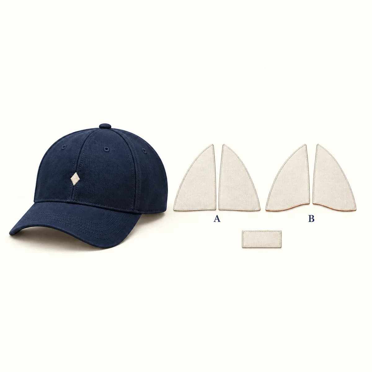
Start with a supported cap that is already selected
A cap buckram request becomes useful to a sourcing team when it identifies a component change that the supplier can review. “Change the front support” leaves the cut-piece outline, its position and its relationship to the assembled crown unresolved. Begin after the team has chosen the supported construction, then draw the particular boundary that needs a decision.
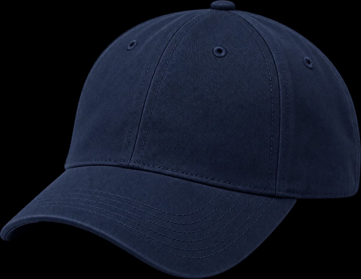
Consider one hypothetical navy six-panel cap with a curved visor and a small front diamond mark. The shell pattern, cloth, visor and artwork remain fixed. S1 identifies the supplied front-shaping support reference. A is the starting cut-piece contour; B is a proposed revision using that same reference. The paired front pieces shown in the illustrations belong to this development example. They do not identify FORMBRIM stock, a material grade or an approved production pattern.
Outdoor Cap describes buckram in the front crown panels as a shaping component. That provides component terminology, not a contour specification for this project. If the team still needs to choose a structured or softer crown, resolve that in the existing construction guide first. Here the deliverable is a support drawing and a focused next-sample instruction.
Map upper, side and lower support boundaries
Put the front-panel drawing and the proposed support contour in the same orientation. Show the shell outline, panel joins and lower band interface as distinct references. Give the support its own continuous outline so a reviewer can follow its upper limit, both side limits and lower edge without mistaking a shell seam for the edge of S1.
At the upper boundary, mark where the support proposal ends relative to the front-panel outline. At each side, show its relationship to the join with the adjoining crown panel. At the lower boundary, show where it approaches the band assembly. These are drawing relationships to resolve with the supplier; none establishes a universal distance or an ideal amount of coverage.
Keep A and B at the same scale and retain their orientation marks. In this example, their upper and side contours match. B changes only a small central portion of the lower edge. The change can therefore be located directly rather than inferred from two differently sized pieces. A supplier who needs a different upper or side contour should return that as a separately identified proposal.
A small local embroidery-backing reference may appear on the assembly map to prevent confusion with the shaping pieces. Keep it separately identified and subordinate to the contour review. The manufacturer Banqiu lists cap-front interlinings and embroidery-backing products in its application range; those supplier listings do not specify the material or attachment represented by S1.
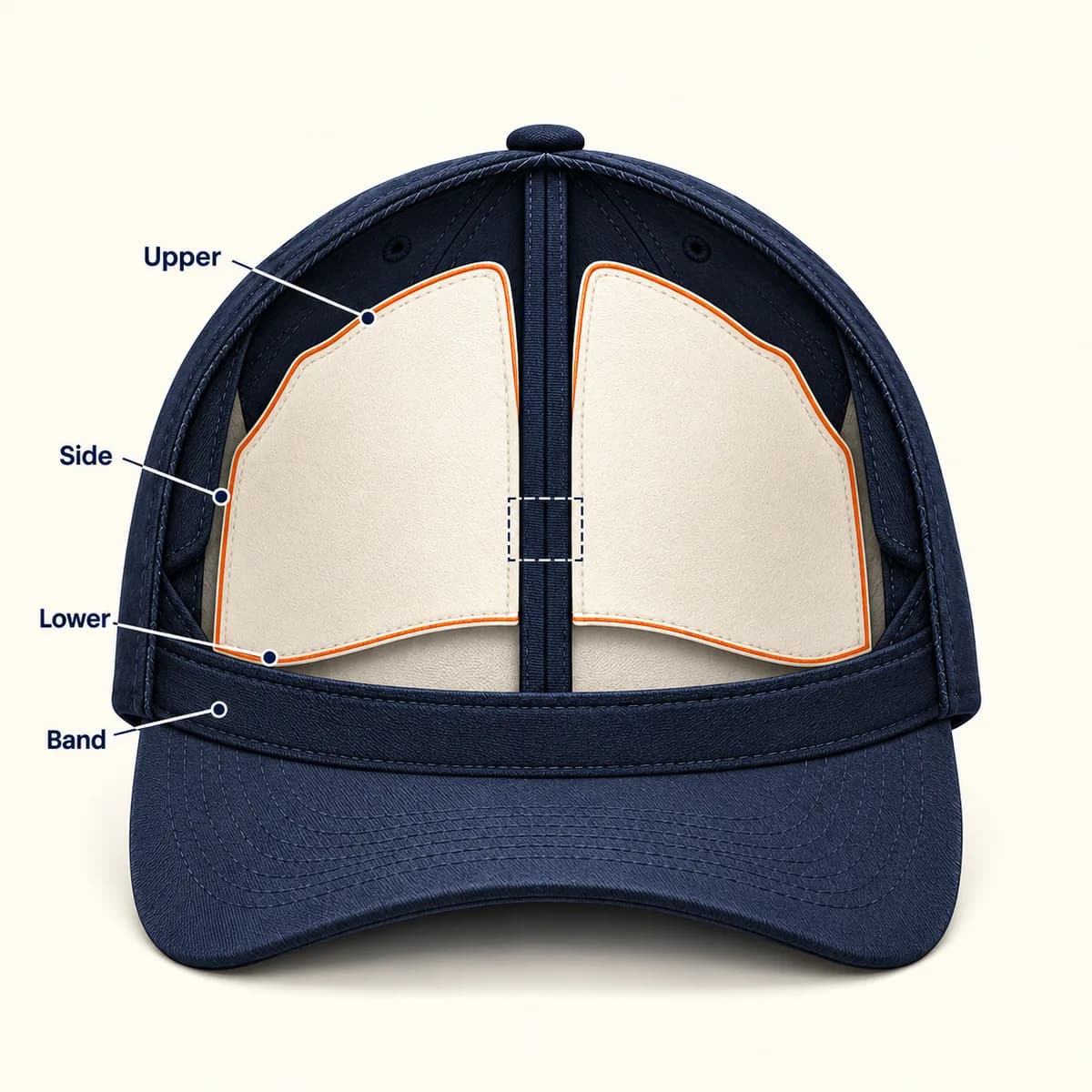
- Trace the shaping-support contour in one orientation.
- Keep panel joins and the lower band visible.
- Identify the small local backing separately.
Locate the contour against the front-panel joins
The center-front join is a shell-assembly reference. The edges of the left and right support pieces are component references. Draw both, including any area where the proposed support edge approaches a join, so the technical supplier can explain their relationship. A pair of loose pieces alone does not show how the proposal sits in the assembled front.
Ask the supplier to mark which line is a cut edge, which is a panel join and where the intended inside finish is represented. If the drawn support boundary and proposed assembly cannot be reconciled, keep that junction open for technical review. Request an annotated construction view rather than assuming that the visible outline also defines a sewing allowance or attachment line.
Hold the shell joins and small artwork position fixed while this question is answered. Moving the center seam, changing the front-panel shape or relocating the mark would create a wider revision. If the supplier proposes one of those changes, identify it explicitly and ask which accepted reference would need to reopen. The A/B support comparison should remain understandable on its own.
Resolve one lower-edge and band-interface proposal
Use the lower central boundary as the single revision in this example. A retains the starting line. B raises a short central part of that line while its upper and side boundaries remain unchanged. This is a contour to discuss, not a recommendation that a higher edge will improve the cap. The illustration deliberately leaves the attachment treatment unresolved.
Send the supplier the A/B overlay and ask: how would the proposed B edge relate to the band assembly and the center-front inside finish? Request a marked inside view or a local section that identifies the support edge, shell and band interface. Have the supplier state whether B is feasible with the retained construction, or return a named alternative for the buyer to consider.
Do not turn the drawing gap into an assumed dimension. The technical response must define the project-specific edge and attachment proposal before a sample instruction is finalized. A generic direction to fold, fuse or trim the support would skip that decision. If implementing B requires another component or an attachment change, record that addition rather than treating B as a contour-only substitution.
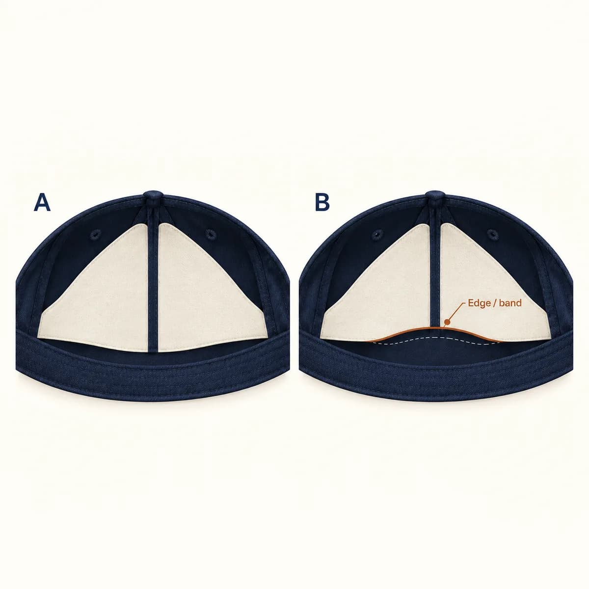
- Retain the upper and side support boundaries.
- Ask how B relates to the band assembly.
- Record the agreed edge in the component revision.
Carry the named contour into the assembled sample
Once the technical parties agree what to sample, connect the returned construction proposal to its drawing revision. Keep S1, the selected contour and the resolved lower-edge treatment together. If the supplier changes the support reference as well as the outline, create a new component revision; a different supplied support should not inherit the S1 label merely because it looks similar.
Request an assembled front view and an inside view that locate the revised lower edge against the same center join and band interface. Where the finished assembly conceals the edge, agree what accompanying construction evidence can show its position. A complete-cap photograph alone may not reveal whether the requested contour was represented.
Compare the returned sample with the retained cap drawing and the named component proposal. Record whether the intended interface is represented and whether any shell, visor or artwork feature changed. If a detail remains unclear, identify that local gap and request clarification. Do not approve an unseen edge on the strength of an attractive outer silhouette.
Send a component drawing and BOM revision request
The purchasing handoff should tell the supplier what is changing and what remains accepted. For this example, request technical review of contour B on support reference S1, specifically its lower central boundary and relationship to the band assembly. Retain the upper and side contours, shell pattern, cloth, visor and small artwork unless a separately identified proposal is returned.
After the technical response, carry the agreed contour and attachment description into the component drawing and bill of materials revision. Name one next whole-cap sample request and the person responsible for resolving the open interface. This is more actionable than asking for a generally softer, stronger or more comfortable front.
FORMBRIM develops OEM/ODM headwear with a published minimum of 300 pieces per style, per color. Send the fixed cap reference and marked component proposal when discussing a bulk project. Material availability and the feasible support-edge construction need project-specific confirmation.
- Support reference: S1, with the supplied reference retained for review.
- Contour revision: A as the starting outline; B as the proposed lower-central-edge change.
- Open interface: supplier to resolve the B edge at the band and center-front inside finish.
- Retained features: upper and side support contours, shell, cloth, visor and artwork.
- Next request: one whole-cap sample representing the agreed component drawing revision.